Project Summary
In this project a 3D-printable shelf bracket was designed. By using traditional design methods in combination with generative design software tools, a unique and functional shape was created. Prototypes were then printed and used at our guild room!
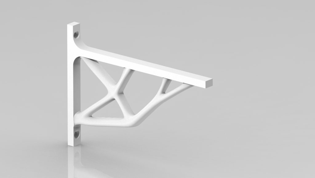
Figure 1: Rendering of the finished 3D-model
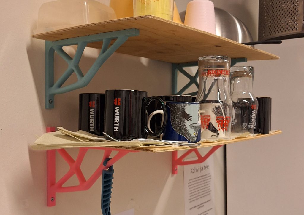
Figure 2: Prototypes in use!
Why?
Our guild room needed a shelf to organize all of the coffee cups and some other things. We also had spare plywood available to be used as the shelf itself, so I thought that designing a custom bracket would make for an interesting project! It was also a good chance to utilize topology optimization tools and the design freedom provided by 3D-printing. I would also like to emphasize, that the purpose of this project was by no means to create the most efficient, cheap or lightweight bracket design. The goal for me was to create an interesting shape with a high degree of functionality, while keeping the need for printing supports minimal!
The Design Process
Design starting points
From the start, the design was strongly influenced by the following factors: Firstly, the part was going to be 3D-printed, and this meant that the build volume of the printer would dictate the maximum possible size. Another consideration related to 3D-printing is the orientation of the part. For material extrusion type printing processes, avoiding interlayer shear is desired. Considering this, it was decided that the part should be printed on its side. There was still a small concern regarding the shear around mounting holes, which is why a high factor of safety was used when modelling the load cases. It was also decided at an early stage that the shelf would be attached using adhesive mounting tape that was available to us, and this meant that there was no need to consider screws on the shelf mounting surface.
Approximating the loading
It is reasonable to assume, that a typical coffee cup weighs around 200 to 400 grams when empty. Assuming that the maximum amount of coffee cups stored on the shelf at any given time is no more than 20, we can round up the weight to be 10 kilograms. This includes the the plywood sheet. A single bracket would therefore have to withstand a static force of around 50 Newtons, but due to anisotropic properties of 3D-printed parts as well as possible stress concentrations, especially around mounting holes I chose to use a load factor of 8! Not the most efficient but due to many approximations and unknowns it is better to be safe than sorry! Also, in this project the overall material consumption will be relatively low in any case, so there is no significantly negative impact in doing this.
Optimization of geometry with Creo’s generative design extension
First, the design space for the part was established. This was done by simply extruding a planar sketch which has the rough outline of the final product shape. Next, the geometry to be preserved was defined. In this case it was done by extruding the profile inside the original body as depicted in figure 4. This new extrusion was defined as a new body. Then, the areas where material is not wanted were defined in a similar way as the previous step. This extrusion was also defined as a separate body.
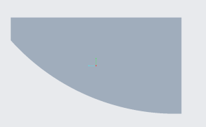
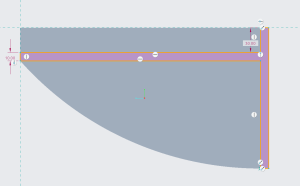
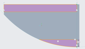
Figures 3, 4 and 5: Starting geometry body, preserved geometry sketch, excluded geometry sketch all viewed from side view
Finally, the attachment holes and rounds were added to the preserved body. The rounds were added to avoid stress concentrations caused by sharp angles in geometry.
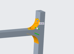
Figure 6: Rounds reduce stress concentrations
After establishing the geometries model was optimized using Creo’s “Generative Design” – extension. Design criteria was assigned to maximize stiffness while limiting the maximum volume of the final part to 40%. Displacement constraints were applied to mounting holes as well as the backside of the bracket. A force load of 400 Newtons was applied to the surface onto which the shelf will be mounted. In the spirit of “Design for Manufacturing” (DFM), a “linear extrude”- constraint was added to one side. This ensures that one of the sides will be flat, which eliminates the need for practically all support structures during the printing process.
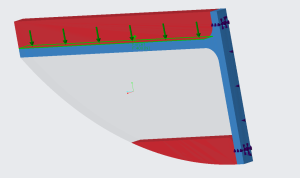
Figure 7: Generative design setup. Note the different geometry bodies defined early; Preserved (Blue) and Excluded (Red) geometries lie both completely inside the starting geometry (Transparent) body.
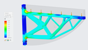
Figure 8: Von Mises stress distribution for one of the design iterations. The stress is within the common yield values for polylactic acid (PLA) but it is important to keep in mind that the 3D-printed part will be partially hollow and is affected by anisotropy due to layered structure. This model assumes that the part is a continuous solid, and should not be relied on entirely. It does however give a general sense of the stress magnitudes and also how the geometry handles the load.
After several iterations of optimization and trying different parameters, a desired shape was reached. It was then reconstructed as a solid body and also exported in STL-format for 3D-printing.
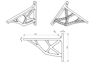
Figure 9: Some key dimensions for the bracket
Manufacturing and the final result
The prototype models were printed out of regular PLA-filament by my friend, who also optimized the key printing parameters. The wall count was raised to 5 to reinforce the print. Infill density was set to 15% and it used a gyroid pattern. Layer height was set to be adaptive in range of 0.2 to 0.8 millimeters. With these parameters the total material consumption for a single bracket was estimated by the slicer software to be 82 grams. Assuming that a kilogram of PLA-filament costs around 25 euros, the material cost for a single bracket is less than 2.5 euros. Not bad for a functional prototype manufactured in less than 3 hours!
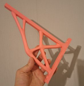
Figure 10: Finished print
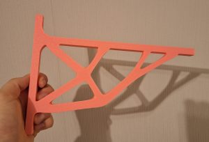
Figure 11: Backside of the bracket. The flat surface allowed for efficient printing of the model.