Introduction
This project is a throwback to early 2025 when we decided that in order to improve our frame design, driver ergonomics would have to be considered in more detail. While there are several good references for general ergonomics design, everyone is different and individual driver feedback is extremely valuable. One approach that has been done by many teams in the past is to build a physical testing jig in which the drivers can sit and adjust key ergonomic parameters such as seat angle, steering wheel position as well as pedal box distance. Being the frame designer for our team, I decided to build one as well!
Design process
In principle, the jig can be as simple or as complex as the team wants it to be. The main trade-offs being information gained, ease of use, durability, and at the time the most important: cost of manufacturing. As a starting point, there were two major constraints that were the driving factors behind most design decisions.
- The material costs would have to be kept as low as possible. We were fortunate enough to receive some wood materials as a donation, as well as to have access to basic woodworking equipment. Therefore, main costs for this project were related to metal hardware such as screws.
- After completing the testing, we would have the option to store this jig in a pallet storage system, and thus the design would have to fit on a standard “EUR-pallet” when disassembled.
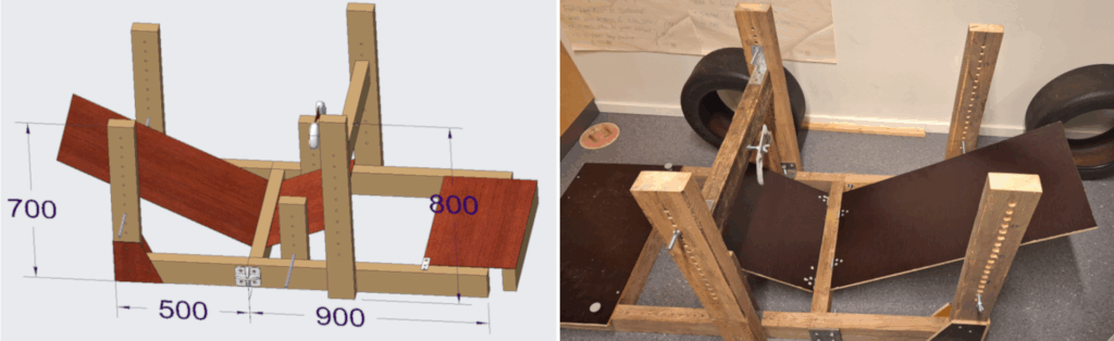
These constraints streamlined the design process significantly, since only the materials donated to us could be used. Right from the start I decided that due to having very little experience in woodworking, I would first model the design in relatively high detail with CAD-software. This would make it possible to easily get all the right dimensions and templates for cuts, as well as to estimate the cost of parts that need to be bought. Additionally, assembling everything digitally would ensure the proper fit of parts both in the jig as well as the EUR-pallet. The final CAD-models for both assembled and disassembled states of the jig can be seen in figure 2.
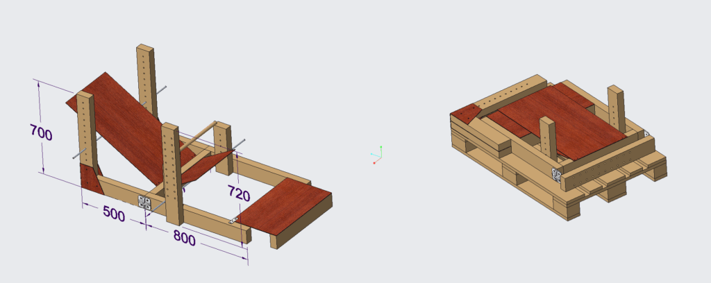
Now, was detailed modelling really necessary for such a simple structure? Likely not… Was it a significant help and a confidence booster for a woodworking novice such as me? Definitely!
The build, measurements and results
The building process itself went relatively well since all the working steps were clear from the start. Still, the most surprising part was the amount of time that even the basic tasks required. The task that turned out to be the most tedious one was measuring, marking and drilling all the holes required for the adjustment mechanisms. Overall, turning a digital design into an actual physical product by hand was certainly a great experience!
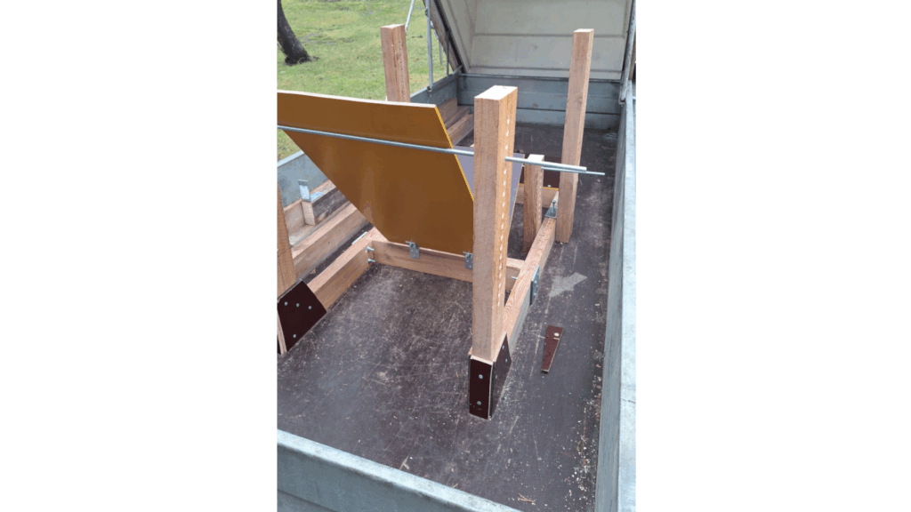
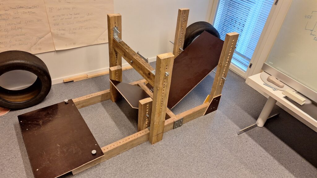
The constructed jig is shown in figures 3-5.
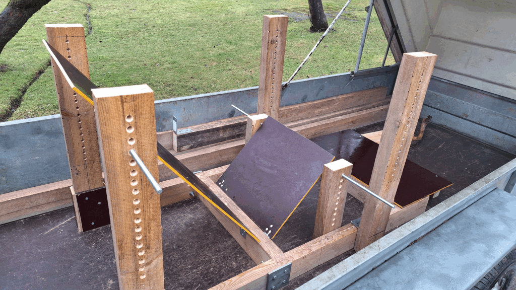
After having several team members test the jig and give feedback, we decided that a reclined driving position would be most optimal. Measuring the key parameters such as seat and thigh angles from the jig enabled us to draw a 2D-sketch of the desired driving position. This sketch would later serve as one of the guiding templates in the main skeleton model of the CAD-assembly! Stay tuned for more project updates!